Sterling Type 54A Transmitter
Sterling Telephone & Electric Co. Ltd.; London
- Land
- Grossbritannien (UK)
- Hersteller / Marke
- Sterling Telephone & Electric Co. Ltd.; London
- Jahr
- 1916
- Kategorie
- Kommerzieller Sender (nicht Sende-Empfänger)
- Radiomuseum.org ID
- 276045

Klicken Sie auf den Schaltplanausschnitt, um diesen kostenlos als Dokument anzufordern.
- Hauptprinzip
- Sender
- Wellenbereiche
- Wellen in den Bemerkungen.
- Betriebsart / Volt
- Akku und/oder Batterie / 24 Volt
- Lautsprecher
- - - Kein Ausgang für Schallwiedergabe.
- Material
- Metallausführung
- von Radiomuseum.org
- Modell: Sterling Type 54A Transmitter - Sterling Telephone & Electric
- Form
- Chassis - Einbaugerät
- Bemerkung
-
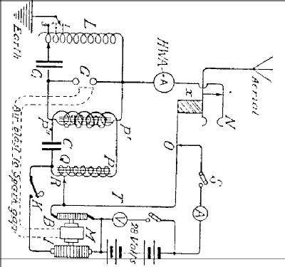
The Sterling Type 54A Transmitter was used on long range patrol aircraft and night bombers.
The input to the spark transmitter was 120 Watt and powered by an alternator driven by a wind screw placed in the slipstream of the propeller. The frequency range was from 200-335 & 500-600 metres. This achieved a working range of 80km.
It was powered by an alternator driven by a wind screw placed in the slipstream of the propeller. The input power was 120 Watts at 24V and powered from a 24B battery.
A motor driven rotary interrupter, (“I” on schematic) with a tuned transformer “P”,”Q”,”R”,”C” gave improved efficiency. A socket “N” was the aerial connection and an insulating block “X” switched off the motor when the receiving plug was inserted. The spark gap could be ventilated by means of an air blast from the motor. A set consisted of three units; Transmitter, rotary interrupter and accumulators.
- Nettogewicht
- 20 kg / 44 lb 0.8 oz (44.053 lb)
- Literaturnachweis
- HRSA Radiowaves, No. 23 January 1988
- Autor
- Modellseite von Gary Cowans angelegt. Siehe bei "Änderungsvorschlag" für weitere Mitarbeit.
- Weitere Modelle
-
Hier finden Sie 39 Modelle, davon 33 mit Bildern und 6 mit Schaltbildern.
Alle gelisteten Radios usw. von Sterling Telephone & Electric Co. Ltd.; London
Literatur
Das Modell Sterling Type 54A Transmitter ist in der folgenden Literatur dokumentiert.