Sterling Type 54A Transmitter
Sterling Telephone & Electric Co. Ltd.; London
- País
- Gran Bretaña (GB)
- Fabricante / Marca
- Sterling Telephone & Electric Co. Ltd.; London
- Año
- 1916
- Categoría
- Transmisor comercial (TX no transceptor)
- Radiomuseum.org ID
- 276045

Haga clic en la miniatura esquemática para solicitarlo como documento gratuito.
- Principio principal
- Transmitter
- Gama de ondas
- Bandas de recepción puestas en notas.
- Tensión de funcionamiento
- Baterías recargables o pilas / 24 Volt
- Altavoz
- - - No hay salida de sonido.
- Material
- Metálico
- de Radiomuseum.org
- Modelo: Sterling Type 54A Transmitter - Sterling Telephone & Electric
- Forma
- Chasis (tambien de autoradio)
- Anotaciones
-
The Sterling Type 54A Transmitter was used on long range patrol aircraft and night bombers.
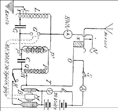
The input to the spark transmitter was 120 Watt and powered by an alternator driven by a wind screw placed in the slipstream of the propeller. The frequency range was from 200-335 & 500-600 metres. This achieved a working range of 80km.
It was powered by an alternator driven by a wind screw placed in the slipstream of the propeller. The input power was 120 Watts at 24V and powered from a 24B battery.
A motor driven rotary interrupter, (“I” on schematic) with a tuned transformer “P”,”Q”,”R”,”C” gave improved efficiency. A socket “N” was the aerial connection and an insulating block “X” switched off the motor when the receiving plug was inserted. The spark gap could be ventilated by means of an air blast from the motor. A set consisted of three units; Transmitter, rotary interrupter and accumulators.
- Peso neto
- 20 kg / 44 lb 0.8 oz (44.053 lb)
- Mencionado en
- HRSA Radiowaves, No. 23 January 1988
- Autor
- Modelo creado por Gary Cowans. Ver en "Modificar Ficha" los participantes posteriores.
- Otros modelos
-
Donde encontrará 39 modelos, 33 con imágenes y 6 con esquemas.
Ir al listado general de Sterling Telephone & Electric Co. Ltd.; London
Literatura
El modelo Sterling Type 54A Transmitter está documentado en la siguiente literatura.