Sterling Type 54A Transmitter
Sterling Telephone & Electric Co. Ltd.; London
- Pays
- Royaume Uni
- Fabricant / Marque
- Sterling Telephone & Electric Co. Ltd.; London
- Année
- 1916
- Catégorie
- Émetteur commercial (pas d'émetteur/récepteur)
- Radiomuseum.org ID
- 276045

Cliquez sur la vignette du schéma pour le demander en tant que document gratuit.
- Principe général
- Émetteur
- Gammes d'ondes
- Bandes en notes
- Tension / type courant
- Piles (rechargeables ou/et sèches) / 24 Volt
- Haut-parleur
- - - Pas de sortie basse fréquence
- Matière
- Boitier métallique
- De Radiomuseum.org
- Modèle: Sterling Type 54A Transmitter - Sterling Telephone & Electric
- Forme
- Chassis (pour intégration dans meuble)
- Remarques
-
The Sterling Type 54A Transmitter was used on long range patrol aircraft and night bombers.
The input to the spark transmitter was 120 Watt and powered by an alternator driven by a wind screw placed in the slipstream of the propeller. The frequency range was from 200-335 & 500-600 metres. This achieved a working range of 80km.
It was powered by an alternator driven by a wind screw placed in the slipstream of the propeller. The input power was 120 Watts at 24V and powered from a 24B battery.
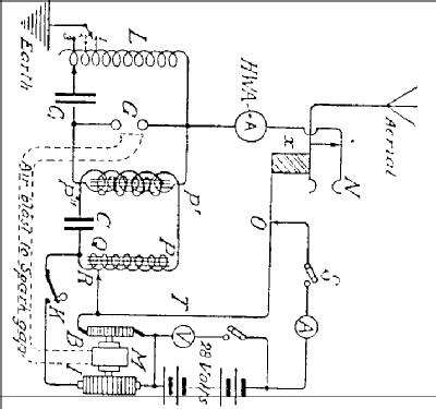
A motor driven rotary interrupter, (“I” on schematic) with a tuned transformer “P”,”Q”,”R”,”C” gave improved efficiency. A socket “N” was the aerial connection and an insulating block “X” switched off the motor when the receiving plug was inserted. The spark gap could be ventilated by means of an air blast from the motor. A set consisted of three units; Transmitter, rotary interrupter and accumulators.
- Poids net
- 20 kg / 44 lb 0.8 oz (44.053 lb)
- Littérature
- HRSA Radiowaves, No. 23 January 1988
- Auteur
- Modèle crée par Gary Cowans. Voir les propositions de modification pour les contributeurs supplémentaires.
- D'autres Modèles
-
Vous pourrez trouver sous ce lien 39 modèles d'appareils, 33 avec des images et 6 avec des schémas.
Tous les appareils de Sterling Telephone & Electric Co. Ltd.; London
Littérature
Le modèle Sterling Type 54A Transmitter est documenté dans la littérature suivante.