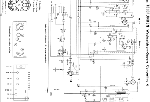
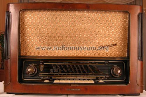
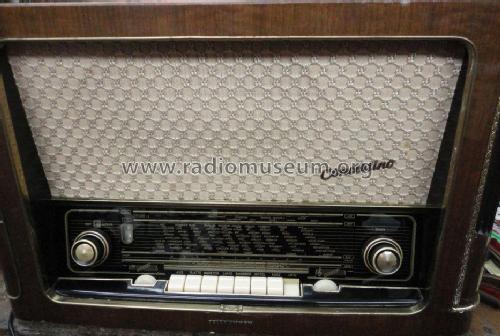
Concertino 6 Wechselstrom
Telefunken Deutschland (TFK), (Gesellschaft für drahtlose Telegraphie Telefunken mbH
- Hersteller / Marke
- Telefunken Deutschland (TFK), (Gesellschaft für drahtlose Telegraphie Telefunken mbH
- Jahr
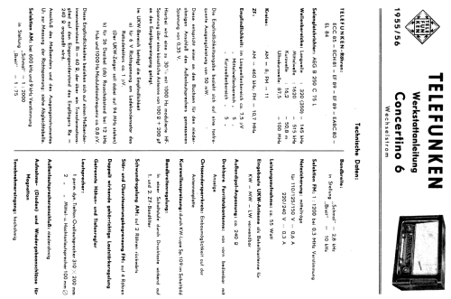
- 1955/1956
- Kategorie
- Rundfunkempfänger (Radio - oder Tuner nach WW2)
- Radiomuseum.org ID
- 20474


Telefunken Concertiono 6 Chassis von vorne
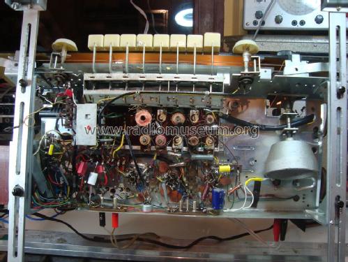
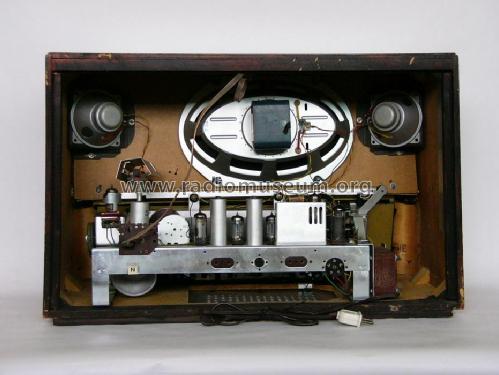
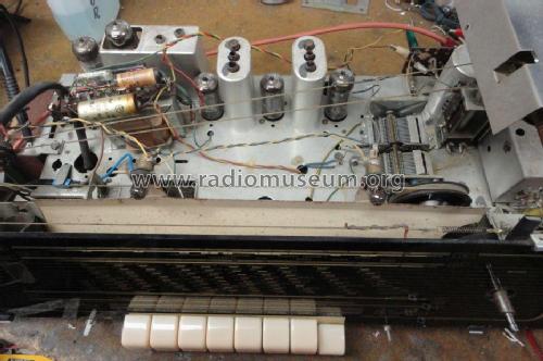
Telefunken Concertion 6 Chassis von unten


Klicken Sie auf den Schaltplanausschnitt, um diesen kostenlos als Dokument anzufordern.
- Anzahl Röhren
- 7
- Anzahl Transistoren
- Halbleiter
- B250C75
- Hauptprinzip
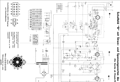
- Superhet allgemein; ZF/IF 460/10700 kHz
- Anzahl Kreise
- 8 Kreis(e) AM 11 Kreis(e) FM
- Wellenbereiche
- Langwelle, Mittelwelle, Kurzwelle und UKW.
- Betriebsart / Volt
- Wechselstromspeisung / 110, 125, 150, 220, 240 Volt
- Lautsprecher
- 3 Lautsprecher
- Belastbarkeit / Leistung
- 5 W (Qualität unbekannt)
- Material
- Gerät mit Holzgehäuse
- von Radiomuseum.org
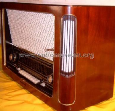
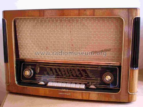
- Modell: Concertino 6 [Wechselstrom] - Telefunken Deutschland TFK,
- Form
- Tischgerät, Tasten oder Druckknöpfe.
- Abmessungen (BHT)
- 640 x 405 x 275 mm / 25.2 x 15.9 x 10.8 inch
- Bemerkung
-
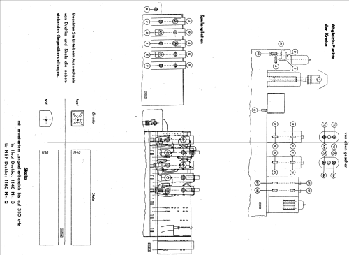
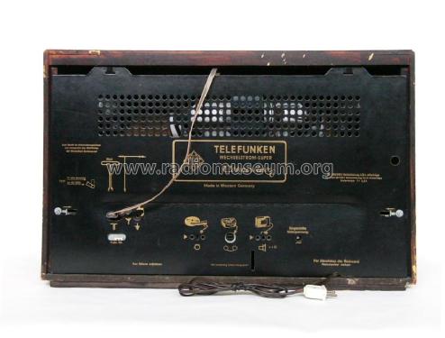
UKW-Skala mit Ätzstreifen zur Markierung der Sender; KW-Lupe. Chassis baugleich mit AEG 4075WD.
Internal ferrite antenna rotating by control that is coaxial to the volume pin.
Separate controls for bass and treble with position indicator.
Woofer impedance: 4 Ω, Tweeter impedance (two in parallel): 5 Ω.
- Nettogewicht
- 14.5 kg / 31 lb 15 oz (31.938 lb)
- Originalpreis
- 419.00 DM
- Datenherkunft extern
- Erb
- Datenherkunft
- HdB d.Rdf-& Ferns-GrH 1955/56
- Weitere Modelle
-
Hier finden Sie 3580 Modelle, davon 3167 mit Bildern und 2123 mit Schaltbildern.
Alle gelisteten Radios usw. von Telefunken Deutschland (TFK), (Gesellschaft für drahtlose Telegraphie Telefunken mbH
Sammlungen
Das Modell Concertino befindet sich in den Sammlungen folgender Mitglieder.
Forumsbeiträge zum Modell: Telefunken: Concertino 6
Threads: 1 | Posts: 13
hello to all members , thanks again for the help to determinate the correct model , on the first look detect changes on the power supply (cams from same old technician) , this guy cut the AC selector ( 240v ,220v ,150v ,125v ,110v ) of the radio and the original AEG B 300 C 75 diode... .
As replacement diode use the B280C 800Si ( old technician replacement not my choice. )
Before plug the radio again to my country power source ( 230v ), remove all tubs of the radio and measure the high voltage on the pins 7 and 9 of EL84 tube, pin 9 give me 350v dc pin 7 give me 340v dc .The original schematic have on pin 7 250v dc and on pin 9 230v dc . Hear i need help, how to tune the voltage of the power supply with the correct voltage , please give me advice ,is very important to me on my country is very hard to find a specialist to repair the radio .
Photos of transformer and the diode :
![]()

Thanks very mach
Pantelis Vasileiou, 28.May.12