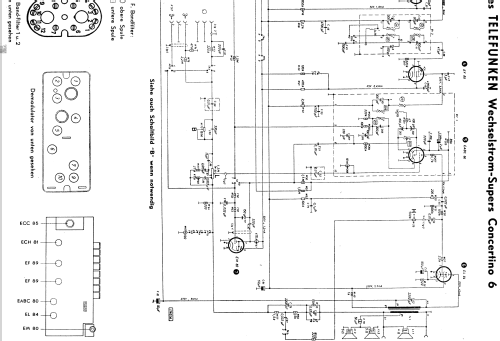
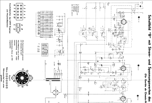
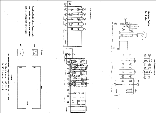
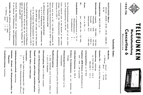
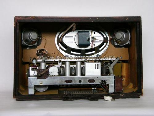
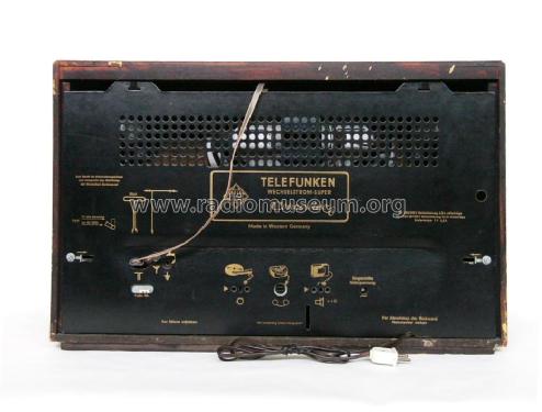
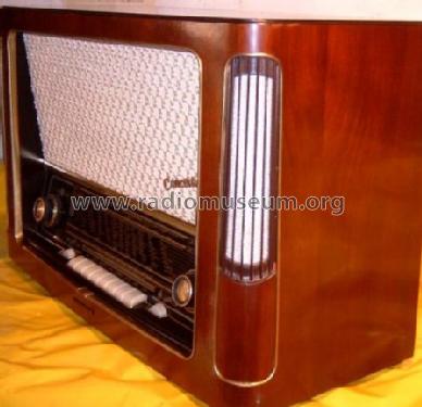
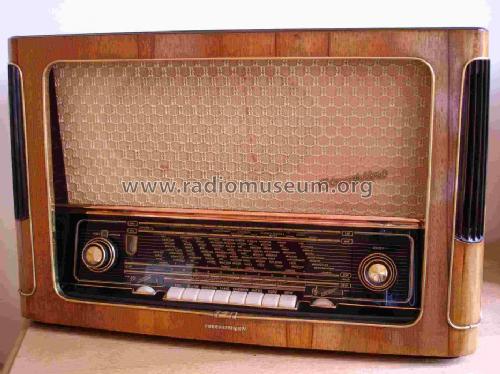
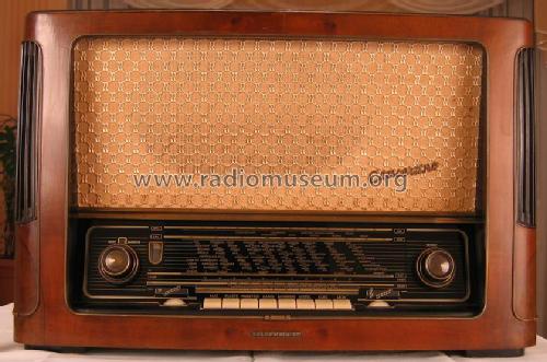
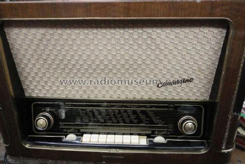
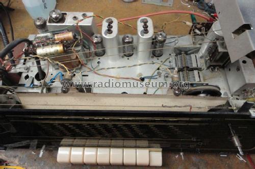
Concertino 6 Wechselstrom
Telefunken Deutschland (TFK), (Gesellschaft für drahtlose Telegraphie Telefunken mbH
- Pays
- Allemagne
- Fabricant / Marque
- Telefunken Deutschland (TFK), (Gesellschaft für drahtlose Telegraphie Telefunken mbH
- Année
- 1955/1956
- Catégorie
- Radio - ou tuner d'après la guerre 1939-45
- Radiomuseum.org ID
- 20474
Cliquez sur la vignette du schéma pour le demander en tant que document gratuit.
- No. de tubes
- 7
- No. de transistors
- Semi-conducteurs
- B250C75
- Principe général
- Super hétérodyne (en général); FI/IF 460/10700 kHz
- Circuits accordés
- 8 Circuits MA (AM) 11 Circuits MF (FM)
- Gammes d'ondes
- PO, GO, OC et FM
- Tension / type courant
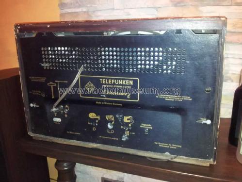
- Alimentation Courant Alternatif (CA) / 110, 125, 150, 220, 240 Volt
- Haut-parleur
- 3 HP
- Puissance de sortie
- 5 W (qualité inconnue)
- Matière
- Boitier en bois
- De Radiomuseum.org
- Modèle: Concertino 6 [Wechselstrom] - Telefunken Deutschland TFK,
- Forme
- Modèle de table avec boutons poussoirs.
- Dimensions (LHP)
- 640 x 405 x 275 mm / 25.2 x 15.9 x 10.8 inch
- Remarques
-
UKW-Skala mit Ätzstreifen zur Markierung der Sender; KW-Lupe. Chassis baugleich mit AEG 4075WD.
Internal ferrite antenna rotating by control that is coaxial to the volume pin.
Separate controls for bass and treble with position indicator.
Woofer impedance: 4 Ω, Tweeter impedance (two in parallel): 5 Ω.
- Poids net
- 14.5 kg / 31 lb 15 oz (31.938 lb)
- Prix de mise sur le marché
- 419.00 DM
- Source extérieure
- Erb
- D'autres Modèles
-
Vous pourrez trouver sous ce lien 3582 modèles d'appareils, 3169 avec des images et 2126 avec des schémas.
Tous les appareils de Telefunken Deutschland (TFK), (Gesellschaft für drahtlose Telegraphie Telefunken mbH
Collections
Le modèle Concertino fait partie des collections des membres suivants.
Contributions du forum pour ce modèle: Telefunken: Concertino 6
Discussions: 1 | Publications: 13
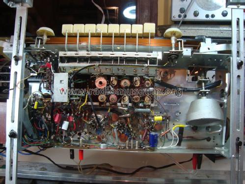
hello to all members , thanks again for the help to determinate the correct model , on the first look detect changes on the power supply (cams from same old technician) , this guy cut the AC selector ( 240v ,220v ,150v ,125v ,110v ) of the radio and the original AEG B 300 C 75 diode... .
As replacement diode use the B280C 800Si ( old technician replacement not my choice. )
Before plug the radio again to my country power source ( 230v ), remove all tubs of the radio and measure the high voltage on the pins 7 and 9 of EL84 tube, pin 9 give me 350v dc pin 7 give me 340v dc .The original schematic have on pin 7 250v dc and on pin 9 230v dc . Hear i need help, how to tune the voltage of the power supply with the correct voltage , please give me advice ,is very important to me on my country is very hard to find a specialist to repair the radio .
Photos of transformer and the diode :
Thanks very mach
Pantelis Vasileiou, 28.May.12


