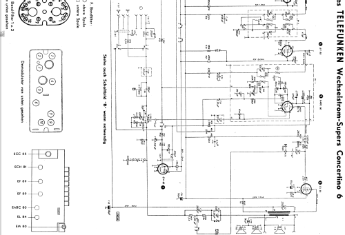
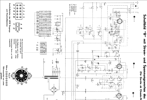
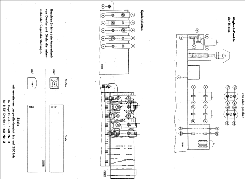
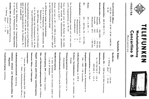
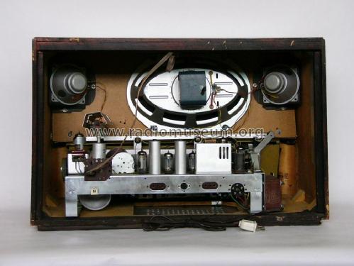
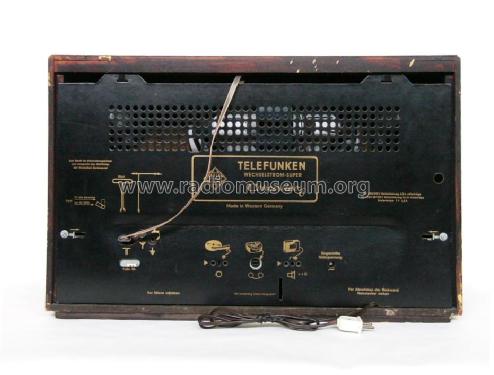
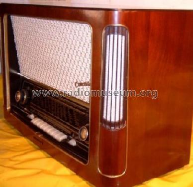
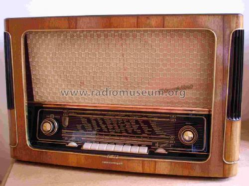
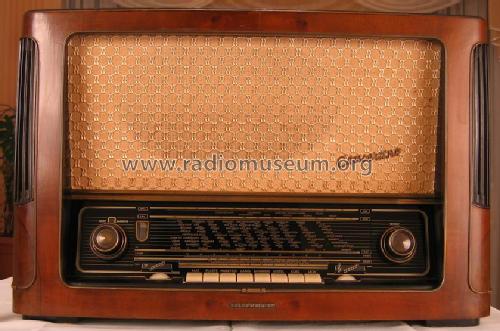
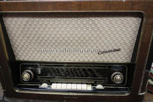
Concertino 6 Wechselstrom
Telefunken Deutschland (TFK), (Gesellschaft für drahtlose Telegraphie Telefunken mbH
- Paese
- Germania
- Produttore / Marca
- Telefunken Deutschland (TFK), (Gesellschaft für drahtlose Telegraphie Telefunken mbH
- Anno
- 1955/1956
- Categoria
- Radio (o sintonizzatore del dopoguerra WW2)
- Radiomuseum.org ID
- 20474
Clicca sulla miniatura dello schema per richiederlo come documento gratuito.
- Numero di tubi
- 7
- Numero di transistor
- Semiconduttori
- B250C75
- Principio generale
- Supereterodina (in generale); ZF/IF 460/10700 kHz
- N. di circuiti accordati
- 8 Circuiti Mod. Amp. (AM) 11 Circuiti Mod. Freq. (FM)
- Gamme d'onda
- Onde medie (OM), lunghe (OL), corte (OC) e MF (FM).
- Tensioni di funzionamento
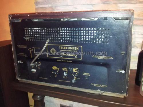
- Alimentazione a corrente alternata (CA) / 110, 125, 150, 220, 240 Volt
- Altoparlante
- 3 altoparlanti
- Potenza d'uscita
- 5 W (qualità ignota)
- Materiali
- Mobile in legno
- Radiomuseum.org
- Modello: Concertino 6 [Wechselstrom] - Telefunken Deutschland TFK,
- Forma
- Soprammobile con pulsantiera/tastiera.
- Dimensioni (LxAxP)
- 640 x 405 x 275 mm / 25.2 x 15.9 x 10.8 inch
- Annotazioni
-
UKW-Skala mit Ätzstreifen zur Markierung der Sender; KW-Lupe. Chassis baugleich mit AEG 4075WD.
Internal ferrite antenna rotating by control that is coaxial to the volume pin.
Separate controls for bass and treble with position indicator.
Woofer impedance: 4 Ω, Tweeter impedance (two in parallel): 5 Ω.
- Peso netto
- 14.5 kg / 31 lb 15 oz (31.938 lb)
- Prezzo nel primo anno
- 419.00 DM
- Fonte esterna dei dati
- Erb
- Fonte dei dati
- HdB d.Rdf-& Ferns-GrH 1955/56
- Altri modelli
-
In questo link sono elencati 3580 modelli, di cui 3167 con immagini e 2123 con schemi.
Elenco delle radio e altri apparecchi della Telefunken Deutschland (TFK), (Gesellschaft für drahtlose Telegraphie Telefunken mbH
Collezioni
Il modello Concertino fa parte delle collezioni dei seguenti membri.
Discussioni nel forum su questo modello: Telefunken: Concertino 6
Argomenti: 1 | Articoli: 13
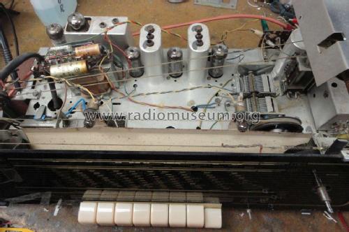
hello to all members , thanks again for the help to determinate the correct model , on the first look detect changes on the power supply (cams from same old technician) , this guy cut the AC selector ( 240v ,220v ,150v ,125v ,110v ) of the radio and the original AEG B 300 C 75 diode... .
As replacement diode use the B280C 800Si ( old technician replacement not my choice. )
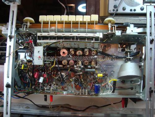
Before plug the radio again to my country power source ( 230v ), remove all tubs of the radio and measure the high voltage on the pins 7 and 9 of EL84 tube, pin 9 give me 350v dc pin 7 give me 340v dc .The original schematic have on pin 7 250v dc and on pin 9 230v dc . Hear i need help, how to tune the voltage of the power supply with the correct voltage , please give me advice ,is very important to me on my country is very hard to find a specialist to repair the radio .
Photos of transformer and the diode :
Thanks very mach
Pantelis Vasileiou, 28.May.12


