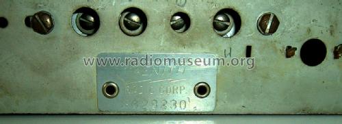
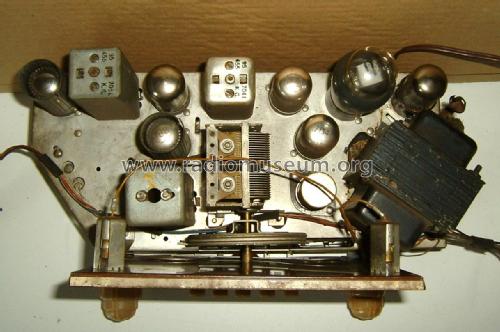
7S558 Chassis 7A02
Zenith Radio Corp.; Chicago, IL
- Country
- United States of America (USA)
- Manufacturer / Brand
- Zenith Radio Corp.; Chicago, IL
- Year
- 1940/1941
- Category
- Broadcast Receiver - or past WW2 Tuner
- Radiomuseum.org ID
- 68028
-
- alternative name: Chicago Radio Lab
Click on the schematic thumbnail to request the schematic as a free document.
- Number of Tubes
- 7
- Main principle
- Superhet with RF-stage; ZF/IF 455 kHz
- Wave bands
- Broadcast and Short Wave (SW).
- Power type and voltage
- Alternating Current supply (AC) / 115 Volt
- Loudspeaker
- Electro Magnetic Dynamic LS (moving-coil with field excitation coil) / Ø 10 inch = 25.4 cm
- Power out
- 6.5 W (unknown quality)
- Material
- Wooden case
- from Radiomuseum.org
- Model: 7S558 Chassis 7A02 - Zenith Radio Corp.; Chicago,
- Shape
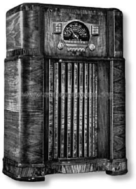
- Console with Push Buttons.
- Dimensions (WHD)
- 0 x 41 x 0 inch / 0 x 1041 x 0 mm
- External source of data
- Ernst Erb
- Source of data
- The Radio Collector's Directory and Price Guide 1921 - 1965
- Circuit diagram reference
- Rider's Perpetual, Volume 12 = ca. 1941 and before
- Mentioned in
- Collector's Guide to Antique Radios 4. Edition
- Literature/Schematics (1)
- Pre-War Consoles
- Other Models
-
Here you find 4517 models, 4109 with images and 3653 with schematics for wireless sets etc. In French: TSF for Télégraphie sans fil.
All listed radios etc. from Zenith Radio Corp.; Chicago, IL
Collections
The model 7S558 is part of the collections of the following members.
Forum contributions about this model: Zenith Radio Corp.;: 7S558 Chassis 7A02
Threads: 1 | Posts: 3
Dear Forum members,
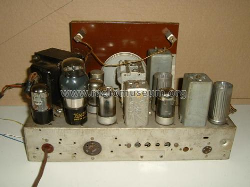
I have a Zenith 7A02 chassis for restauration here. I dowloaded the circuit diagram for this set, and it appears that there is an important difference between this diagram and the chassis i have here. The diagram mentions only two connection points A and G, but the rear ot the radio has a 5-pin connector for the antenna.
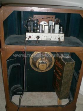
This antenna is a Zenith "Rotor Magnet Wave", as you can see on some of the uploaded pictures.
Can anyone provide me withe the correct circuit diagram please?
Thank you
Attachments
- Antenne ingang (299 KB)
Georges Van Campenhout † 28.4.22, 17.Sep.18


