7S558 Chassis 7A02
Zenith Radio Corp.; Chicago, IL
- Produttore / Marca
- Zenith Radio Corp.; Chicago, IL
- Anno
- 1940/1941
- Categoria
- Radio (o sintonizzatore del dopoguerra WW2)
- Radiomuseum.org ID
- 68028
-
- alternative name: Chicago Radio Lab

Beitman


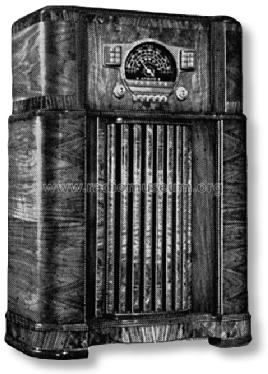
Copy ge. Radio Attic
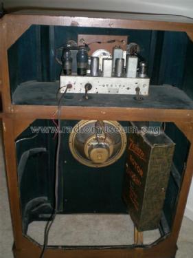


The set belongs to the VRT Omroepmuseum
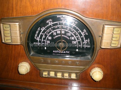
The set belongs to the VRT Omroepmuseum

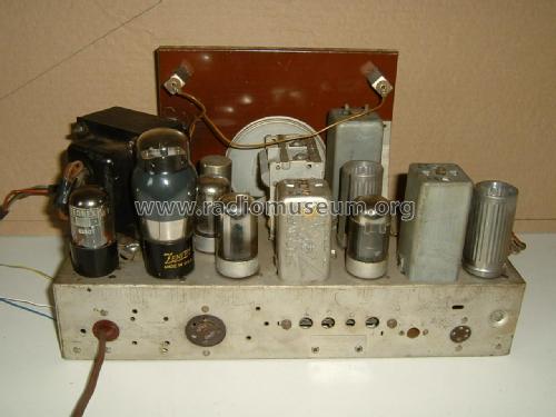
The set belongs to the VRT Omroepmuseum
The set belongs to the VRT Omroepmuseum

The set belongs to the VRT Omroepmuseum

The radio belongs to the VRT Omroepmuseum
Clicca sulla miniatura dello schema per richiederlo come documento gratuito.
- Numero di tubi
- 7
- Principio generale
- Supereterodina con stadio RF; ZF/IF 455 kHz
- Gamme d'onda
- Onde medie (OM) e corte (OC).
- Tensioni di funzionamento
- Alimentazione a corrente alternata (CA) / 115 Volt
- Altoparlante
- AP elettrodinamico (bobina mobile e bobina di eccitazione/di campo) / Ø 10 inch = 25.4 cm
- Potenza d'uscita
- 6.5 W (qualità ignota)
- Materiali
- Mobile in legno
- Radiomuseum.org
- Modello: 7S558 Chassis 7A02 - Zenith Radio Corp.; Chicago,
- Forma
- Console con tastiera/pulsantiera.
- Dimensioni (LxAxP)
- 0 x 41 x 0 inch / 0 x 1041 x 0 mm
- Fonte esterna dei dati
- Ernst Erb
- Fonte dei dati
- The Radio Collector's Directory and Price Guide 1921 - 1965
- Riferimenti schemi
- Rider's Perpetual, Volume 12 = ca. 1941 and before
- Bibliografia
- Collector's Guide to Antique Radios 4. Edition
- Letteratura / Schemi (1)
- Pre-War Consoles
- Altri modelli
-
In questo link sono elencati 4517 modelli, di cui 4109 con immagini e 3653 con schemi.
Elenco delle radio e altri apparecchi della Zenith Radio Corp.; Chicago, IL
Collezioni
Il modello 7S558 fa parte delle collezioni dei seguenti membri.
Discussioni nel forum su questo modello: Zenith Radio Corp.;: 7S558 Chassis 7A02
Argomenti: 1 | Articoli: 3
Dear Forum members,
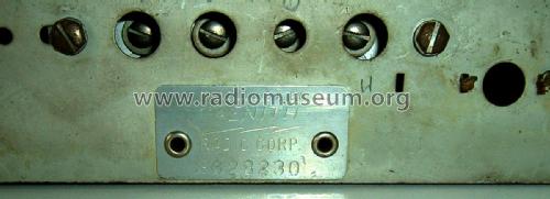
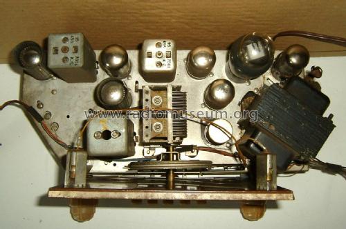
I have a Zenith 7A02 chassis for restauration here. I dowloaded the circuit diagram for this set, and it appears that there is an important difference between this diagram and the chassis i have here. The diagram mentions only two connection points A and G, but the rear ot the radio has a 5-pin connector for the antenna.
This antenna is a Zenith "Rotor Magnet Wave", as you can see on some of the uploaded pictures.
Can anyone provide me withe the correct circuit diagram please?
Thank you
Allegati
- Antenne ingang (299 KB)
Georges Van Campenhout † 28.4.22, 17.Sep.18